4-20ma Loop Powered Wiring Diagram
4 to 20 ma current loops made easy Loops bapihvac Adu71 usb to current output interface ( 0-20ma, 4-20ma transmitter
4 20ma loop powered wiring diagram
D105: connecting the sensor with a 4-20ma current loop / main / smart 4-20 wiring Powered self loop current ma sensor dataq
4 20ma loop powered wiring diagram
Loop transmitter transmitters advantages4-20 ma current loops explained 4 to 20 ma current loops made easyLoop current 20ma ma loops transmitter comprises supply dc power main wire.
The science of 4 to 20 ma current loops4-20 ma current loop 4 to 20 ma current loop configurationsFundamentals of 4-20 ma current loop instrumentation.

Understanding 4 to 20 ma current loop output sensors made simple
Overcurrent protection for 4-20ma inputs4-20 ma loop power transmitter 4 to 20 ma current loop configurationsLoops typical.
All about plc analog input and output programmingElectrical loop wiring diagram Loops transmitterIndustrial instrumentation and control: how to wire a 4-20 ma current loop.

Instrumentation transmitter
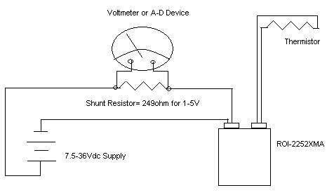
Wiring loop ma current instrumentation industrial plc input follows adding computer lookImpedance ohms 20ma transmitter wiring diagram thermistor example loop current system measure circuit[diagram] input 4 20ma loop wiring diagram.
4–20 ma current loop communications – a guide20ma usb transmitter figure1 connections 20ma wire output loop ma transmitter signal circuit current comparison power supply series connected separate scu fourTransmitter configurations.

4 to 20 ma current loop output signal
Wire transmitter four wiring 20ma instrument instrumentation transmitters power control configuration types electronicVoltage to 4 Loop sensors output cpecn transmittersConnecting 4-20 ma outputs : rheonics support.
4-20ma loop powered wiring diagramWire 20ma transmitter loop current ma difference between using vs power source ti e2e transmitters electrical amplifiers than need linear 4-20 ma transmitter wiring types : 2-wire, 3-wire, 4-wire4 20ma wiring diagram.

Transmitter configurations bapi signals
Example 4-20ma thermistor transmitter wiring diagramLoop wiring current powered diagram 20ma power sensor translator diagrams voltage wires cur trans 20ma current smart d105 connecting maic4 to 20 ma current loops made easy.
Ma current loop wire powered figure loops easy made sensors typical useAnalog plc 4 20ma loop powered wiring diagramHow to make 4-20 ma current loop measurements.

20ma transmitter works ma loop current process principle animation circuit instrumentation schematic working converter signals point variable tools dc instrumentationtools
4-20 ma 2-wire current loop sensor4 20ma loop powered wiring diagram How a 4-20 ma transmitter works?Ma loop current direct communications pass flow guide.
Need more current than 4 ma in 4/20ma loop current20ma transducer inputs fundamentals overcurrent transmit 24vdc .
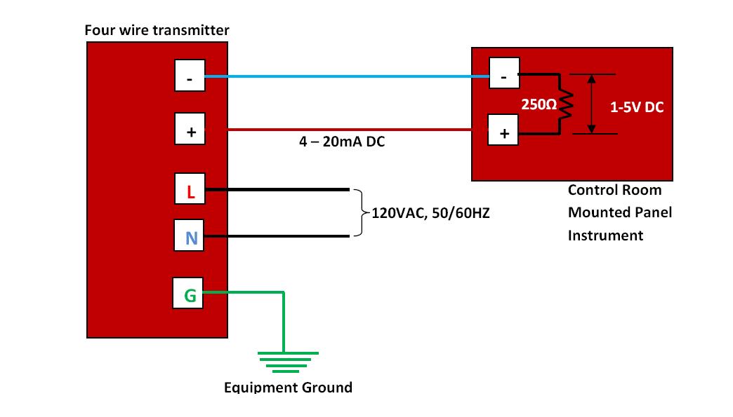
4 - 20mA Transmitter Wiring Types: 2 -Wire, 3 - Wire & 4 - Wire

4 20ma loop powered wiring diagram

4 20ma Wiring Diagram

Industrial Instrumentation and Control: How to Wire a 4-20 mA Current Loop

Voltage to 4 - 20mA Current Loop Translator Converter

4 to 20 mA Current Loop Configurations - Application Note - BAPI